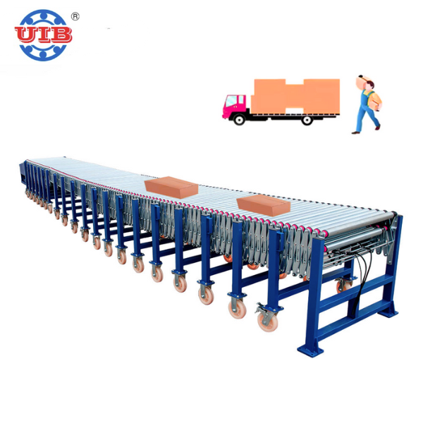
Telescopic roller conveyors just stop working properly when their sensors aren't calibrated right. The segments get out of sync, so rollers spin at different speeds which causes everything to jam up and materials can't move through. We've seen alignment sensors drift over time too, making conveyor sections stick or refuse to retract completely. That forces workers to manually adjust things and sometimes even shut down whole lines for safety. Package spacing gets all messed up, cutting throughput anywhere from 15% to 30%. Worse still, loads end up misaligned, leading to collisions and damaged products throughout the facility. These problems pile up as they move downstream. Workstations sit idle waiting for materials, costing companies around $740,000 each year according to Ponemon Institute research from last year. Regular sensor checks and recalibrations help avoid all this mess by keeping timing accurate, ensuring smooth extensions and retraction, and maintaining proper load detection throughout the whole system.
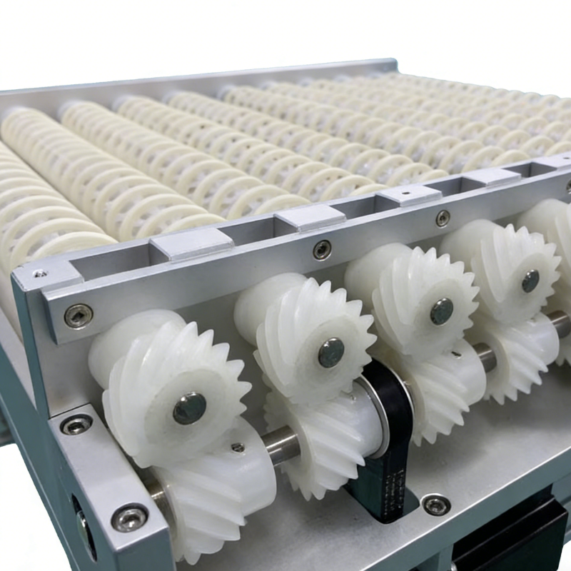
Each sensor type performs distinct, complementary functions essential to dynamic telescopic operation:
When getting ready to calibrate equipment, there are several basics that need checking first. The power supply must be stable with no more than 5% voltage variation allowed. Signal wires should all be intact, which means running continuity tests to make sure nothing's broken or loose. And don't forget about mechanical alignment either. Laser tools can help confirm if everything is properly aligned. Studies indicate that around 43 percent of calibration problems actually come down to hidden mechanical issues like frames that aren't straight or rollers mounted incorrectly. These alignment problems mess with sensor readings even when electronics seem fine. Environmental factors matter too. If temperatures swing more than 15 degrees Celsius or humidity goes over 60% relative humidity, sensors just won't give accurate results during calibration. For good measure, always record what the system does before making any changes. Use PLC diagnostics to capture these baseline readings so there's something concrete to compare against after adjustments are made.
Access the PLC interface to dynamically tune optical and capacitive sensors for operational conditions. For optical sensors:
For capacitive sensors, adjust thresholds based on typical load density:
| Material Density | Recommended Threshold |
|---|---|
| Low (foam, thin plastics) | 15–25 pF |
| Medium (corrugated cardboard) | 30–45 pF |
| High (metal containers) | 55–70 pF |
Validate all adjustments using real-time PLC feedback graphs under simulated production speeds. Incremental changes prevent over-compensation—a leading cause of false triggers during extension cycles. Final values must be logged with timestamps in the PLC for auditability and future benchmarking.
Testing in the field means putting equipment through real world stress, not just what happens in a lab setting. When evaluating pneumatic sensors, they need to handle different weights from around 25kg all the way up to 75kg, work at varying conveyor belt speeds between 0.3 meters per second and 1.5 meters per second, and function properly throughout their entire range from completely retracted position to maximum extension. These sensors should spot packages quickly even when dealing with heavier loads, plus keep those air seals tight while moving back and forth rapidly. Well tuned systems typically hit at least 95 percent accuracy rates despite changes in humidity levels and temperature fluctuations. This kind of performance stops problems like pressure drops, slow response times from actuators, and unexpected system jams that can really disrupt operations according to recent findings published by Industrial Automation Journal.
Post-calibration, conduct targeted stress tests to verify robustness:
Record failure rates during sustained peak-throughput cycles. Field data confirms that achieving 98% reliability under real-world edge cases reduces unplanned downtime by 40% . Cross-reference results with PLC error logs to validate end-to-end synchronization across the telescopic roller conveyor, ensuring every segment responds cohesively to sensor input.
 Hot News
UIB Xiamen is a 10-year factory supplying custom conveyor, sorting machine, forklift & material handling machinery for logistics, cold chain & manufacturing. Free customized solution available.
Room 1409, SM International Center, Xingshan Road, Huli District, Xiamen City, Fujian Province, China.
Copyright © 2025 by UIB (Xiamen) Bearing Co., Ltd. Privacy Policy